


Multiple Step Drill – with Qg1
Creating standard and special step drills in the new Qg1 software is simple, while also offering a great deal of flexibility.
Multiple Step Drill – with Qg1
On the one hand, it is possible to create practically any number of steps, so far the blank can accommodate it. To do so, additional steps are simply added and basic data such as diameter, length, step angle and the step type is specified. A choice of straight, S-shaped, convex, concave or profiled steps is available for advanced users.
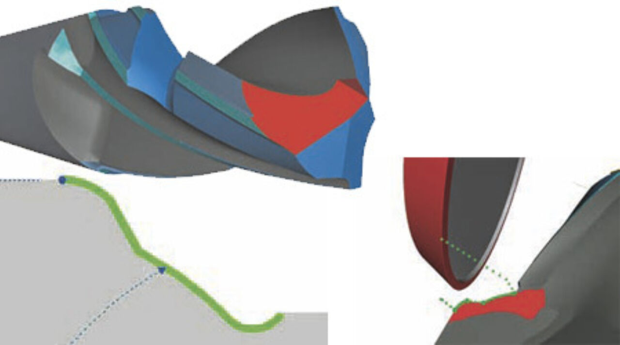
The input values for the step drill are visible
immediately in 2D, and the full drill is
shown in 3D. The currently edited shape
part is highlighted in the cross-section
view [Fig.1].
On the other hand, subland step drills
are quite special. Each step section has
its own rake angle and chip space. Now,
these can be adapted individually for
each step, if necessary. In addition, it’s
been worked on clearance design. Now it
is possible to equip the drill with multiple
cylindrical margins and a middle clearance
between them [Fig.3]. Of course it
can be done on an individual basis for
each step and with twist, if desired.
There is also an option to insert a separate
cutting face for the shaping step,
which is called STEPGASH [Fig.4]. With
the conventional method, the steps are
simply implemented along the contour,
which produces profile distortion in this
area. With an additional cutting face along
the step, the contour is strengthened, profile
distortion is eliminated, and due to the
additional rake angle the chip removing
characteristics are also improved.
The new step drill definition, model and
process calculation are performed entirely
in 3D, based on geoMod (solid
model), and provide a great deal of flexibility
in the design of stepped tools.
Categories
All posts
- GrindingHub 2026 – Thank you for visiting SCHNEEBERGER
- GrindingHub NEWS 5/5: The SCHNEEBERGER Aries NGP grinds and mills ceramic dental implants
- GrindingHub NEWS 4/5: Quinto Qg1 Form Reamers on a new Level
- GrindingHub NEWS 3/5: SCHNEEBERGER’s Sirius NGS Profiles First-Class Indexable Inserts: Threading Inserts and Ball Bearing Grooving Tool
- GrindingHub NEWS 2/5: Next Level of Tap-Production with SCHNEEBERGER Gemini NGM TAP